Chapter 10 : Rotational Motion


Why we need this stuff!


Consider this simple scenario: a heavy beam resting on two jackstands.

  • Apply Newton's Laws to determine the forces each jackstand is exerting on the beam.

    (Hint: you won't be able to find a solution!)

  • What happens if we remove one of them?

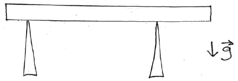
500 kg beam resting on two jackstands

This simple scenario can't be solved using the material prior to this chapter.

The solution will involve looking at the torques being created by each force acting on the beam, and that will be the focus of chapter 12.


Review : Angular vs Linear Motion

Angular-motion

Analogous Linear Motion

\[ \sum \tau = I \alpha \]

\[ \sum \vec{F} = m\vec{a} \]

\[ I = \sum m_i r^2_i = \int r^2 dm \]

just plain old 'mass'

Equations of Motion (if acceleration is constant)

\[ \omega = \omega_o + \alpha t \]

\[ v = v_o + at \]

\[ \theta = \theta_o + \omega_{avg}t \]

\[ x = x_o + v_{avg}t \]

\[ \theta = \theta_o + \omega_o t + \frac{1}{2}\alpha t^2 \]

\[ x = x_o + v_o t + \frac{1}{2}at^2 \]

\[ \omega^2 = \omega^2_o + 2 \alpha \Delta \theta \]

\[ v^2 = v^2_o + 2 a \Delta x \]


Moment of Inertia

Almost everything about rotational motion (angular acceleration, work, energy, power, ... ) involves the moment of inertia of the object.

Wherever mass (m) appears in analyzing linear motion, the moment of inertia (I) appears in the related analysis of angular motion.


Example : Point-Mass Mobile


A (very) simple mobile consists of 3 masses, all in the (X,Y) plane:

  •   10 kg at origin (x=0, y=0)

  •   4 kg at (x=2 m, y=-1 m)

  •   6 kg at (x=2 m, y=4 m)

Compute the moment of inertia (I) about:

  (a) the X axis

  (b) the Z axis

  (c) an axis parallel to Z that passes through the CM of the mobile.


(a real mobile, side view)

(our much simpler one, viewed from above)

Rotation about Z axis about axis parallel to Z but through CM

Location of the Center of Mass (CM)

\[ X_{cm} = \frac{ \sum m_i x_i }{ \sum m_i } = \frac{ (10~kg)(0~m) + (4~kg)( 2~m) + (6~kg)(2~m) }{ (10+4+6)~kg } = 1.0~m \]

\[ Y_{cm} = \frac{ \sum m_i y_i }{ \sum m_i } = \frac{ (10~kg)(0~m) + (4~kg)(-1~m) + (6~kg)(4~m) }{ (10+4+6)~kg } = 1.0~m \]

Parallel-Axis Theorem

If we know the moment of inertia of an object about some axis that passes through it's center of mass, but need to find it's moment of inertia about some other axis that's parallel but offset some distance d :

\[ I = I_{cm} + Md^2 \]


Example : Solid Object (integral!)


  • Determine the moment of inertia of a thin rod of mass M and length L rotating about an axis that passes through one end of the rod, perpendicular to it (the Y axis in the figure).

  • Using the parallel axis theorem, determine the moment of inertia of this object if it's rotating about an axis parallel to Y but passing through it's center of mass.


Moments of Inertia for Common Shapes and Axes

See also: Wikipedia table


Composite Object


Finding 'I' for composite objects is much simpler than the process for finding the overall center-of-mass.

\[ I = \int r^2 dm = \int\limits_{part~1} r^2 dm + \int\limits_{part~2} r^2 dm + \cdots \]

or simply:

\[ I = I_{part~1} + I_{part~2} + \cdots \]

Remember though: 'I' has to be computed about the axis of rotation.

  • Use the moments-of-inertia table for each part.

  • Adjust that value using the parallel-axis theorem as needed to reflect the new axis involved.

  • Note this implies you must start off with a moment of inertia that passes through the CM of the object and is parallel to the axis you ultimately want to rotate about.

The hammer in the figure consists of:

  • Handle: M=5 kg (treat as thin rod)

  • Head: M=10 kg (treat as cylinder)

  • Axis: Y (vertical axis pointing towards the top of the 'page' here, but located 40 cm to the left of the left end of the handle - about where the ball and socket joint in your shoulder would be)


What if we were swinging the hammer is a more normal way, where it's rotating about an axis coming up out of the `page'?

The `I' table in the book doesn't include that geometry, but the Wikipedia table linked above does.

Note this figure uses different axis definitions than I used above.

What we called Y above, they call Z in their figure, for which they give \( I_z = \frac{1}{2}Mr^2 \) (what we used above).

Swinging the hammer in the normal way we'd be rotating about (their) X or Y axes, for which: \( I_x = I_y = \frac{1}{12}M( 3r^2 + h^2 ) \).

Try using this version and the process we used above.


Example: Playground Merry-go-Round


Consider the father pushing a playground merry-go-round as shown in the figure.

He exerts a force of 250 N tangent to the edge of the 200.0 kg merry-go-round, which has a 1.50 m radius.

Consider the merry-go-round itself to be a uniform disk, and ignore friction.

NOTE: a uniform solid disk has a moment of inertia of: I = ½MR2


(a) How much torque is the person providing?   ( \( \tau = rF_{tan} \) )

(b) What angular acceleration will be produced?   ( \( \tau = I \alpha \) )

(c) Suppose we add a (point-mass) 18 kg child 1.25 kg away from the center. What is the moment of inertia now?

(d) If the force is only applied for a quarter-turn (after which the force is removed), what will the angular speed of the ride be? (Assume we started at rest.)   (angular equations of motion)