Chapter 12 : Static Equilibrium |
We've done many problems where multiple forces are involved and applying Newton's Laws (specifically resolving forces into components) has allowed us to determine various unknown forces. | ||||
|
|
|
|
|
Let's apply this process to a very simple scenario where it doesn't work! |
500 kg beam resting on two jackstands |
Statics |
The object isn't linearly accelerating (or even moving) so: ΣF=0 The object isn't angularly accelerating (or even rotating) so: Στ=0 More than that: it isn't angularly accelerating about any axis, so: WE'RE FREE TO CHOOSE WHATEVER 'ROTATION AXIS' WE WANT |
Example : Beam on Two Jackstands | |
A heavy steel beam is resting on two support stands as shown in the figure. How is the object's weight distributed between the supports? (I.e., determine the normal force between the beam and each of the support stands.) |
|
Beam Parameters:
| |
|
Example : Beam on Two Jackstands | |
A heavy steel beam is resting on two support stands as shown in the figure. How is the object's weight distributed between the supports? (I.e., determine the normal force between the beam and each of the support stands.) |
|
Beam Parameters: M=500 kg L=10 m Support 1 : 1 meter from left end of beam Support 2 : 3 meter from right end of beam | |
This time:
Apply \( \sum \tau = 0 \) using an axis coming up out of the page and passing through the
point where the left jackstand is touching the beam.
|
Since you can pick any point to be your 'axis of rotation' for computing torques, how do we pick a GOOD one?
If the object is NOT rotating though (static scenario):
|
Example : Lifting Heavy Log | |
A 20 m long 1000 kg log is being lifted as shown in the figure. If the log is stationary at this point, determine the tension in the cable (which is vertical and is connected to the log at a point 5 m in from the free end), and the normal force at the end of the log on the ground. |
|
| |
If the cable snaps, what would be the instantaneous acceleration of the log? Determine the angular acceleration α as well as the linear acceleration atan of the elevated end of the log.
From moment of inertia table: \( I = \frac{1}{3}ML^2 \) for this shape ('long thin rod' rotating about one end). |
Some Terminology and a (sometimes) Useful Shortcut | |
|
(Fourth way: actual vector cross product...) |
Multiple paths to find the torque each force is creating:
More likely, we'll use the RHR to find the direction (positive or negative) and
find the magnitude of the torque via whichever of these is simpler:
Then don't forget: use RHR to get the SIGN of τ |
Example : Lifting Heavy Log | |
A 20 m long 1000 kg log is being lifted as shown in the figure. If the log is stationary at this point, determine the tension in the cable (which is vertical and is connected to the log at a point 5 m in from the free end). Looking at all the other forces acting on the log, we see that the ground must be exerting forces in both the X and Y directions this time. What does μs need to be (at least) to keep the log from sliding across the ground to the left? |
|
(Hint: we have three unknowns here but if we locate our axis at the point where the log touches the ground, the torques creating by two of the forces will be zero automatically...) |
|
Using an axis of rotation located where the log touches the ground: How much torque is the force of tension creating? \( \tau = r F \sin{\phi} \) Figure shows angle propagation to determine \( \phi \) |
|
Example : Shop Sign | |
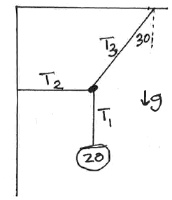
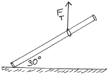
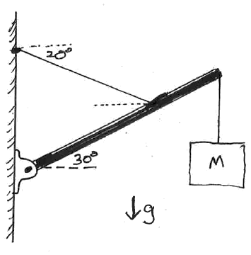
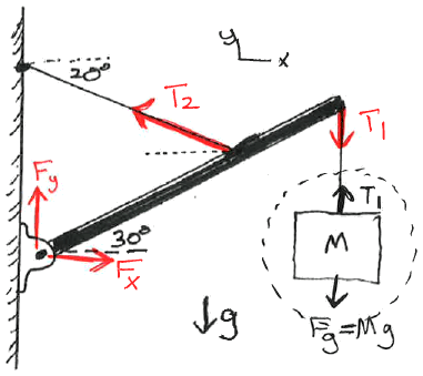
A store sign (of mass M=20 kg) is hanging from the end of a 3 m long pole (of negligible mass) as shown in the figure. The pole makes an angle of 30o up from the horizontal. A support wire is connected from the pole to the building, making an angle of 20o below the horizontal, and connecting to the pole 1 m in from the outer end of the pole. Determine the tensions in the cables and the force(s) the left end of the pole is exerting on the building. (Note: a real pole would have some mass and would contribute to the torque and force calculations, but this example is more about propagating angles.) |
|
Note: the point where the pole is connected to the building is a swivel joint with frictionless ball bearings. It will be exerting X and Y forces on the left end of the pole, but won't introduce any torque itself. (If that end had been, say, welded to the wall, it would introduce a torque, but we'll leave that level of complication to your Statics course.) | |
|
|
Methods for computing torques about the given axis: | |
Torque due to T1
|
Torque due to T2
|
Example : Person Holding Horizontal Pole with Both Hands | |
A pole is being held as shown in the figure. Determine the forces (in terms of the pole weight W=Fg=Mg) the person must be exerting.
(We'll find that Fr will be negative, meaning the person will be pushing down with their right hand, and pulling up with their left hand.) |
|