Photons vs Waves (rays vs fronts)
|
Chapter 34 : The Wave Nature of Light Interference and Polarization |
Photons vs Waves (rays vs fronts) | |
|
|
Effects related to Wave Nature of Light | ||
|
Oil Slick
|
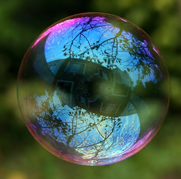
Soap Bubble
|
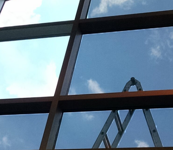
Window Film
|
|
Antennas : Radio, TV, Wireless Router, ...
|
||
Huygen's Principle and Diffraction | |||
|
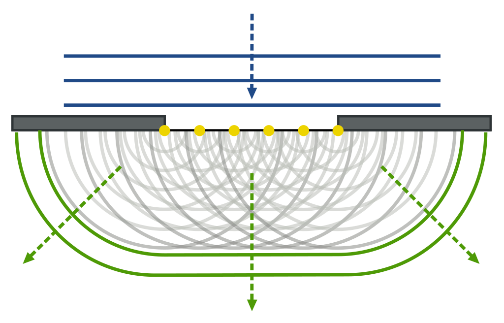
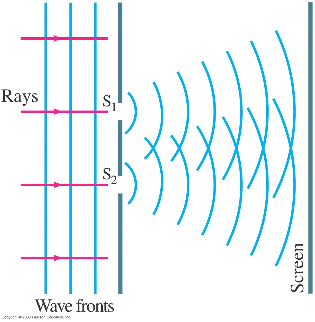
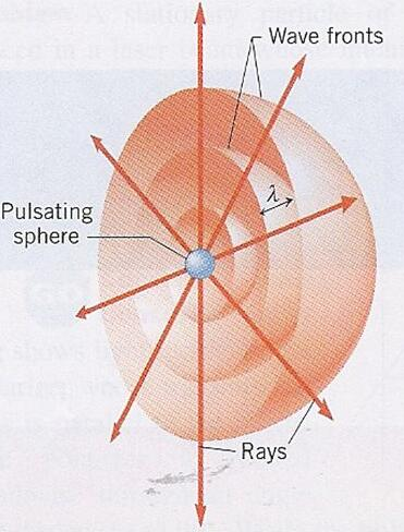
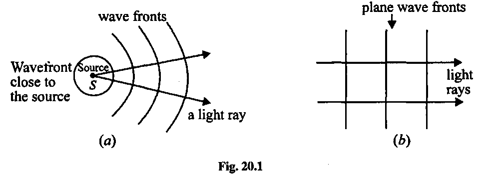
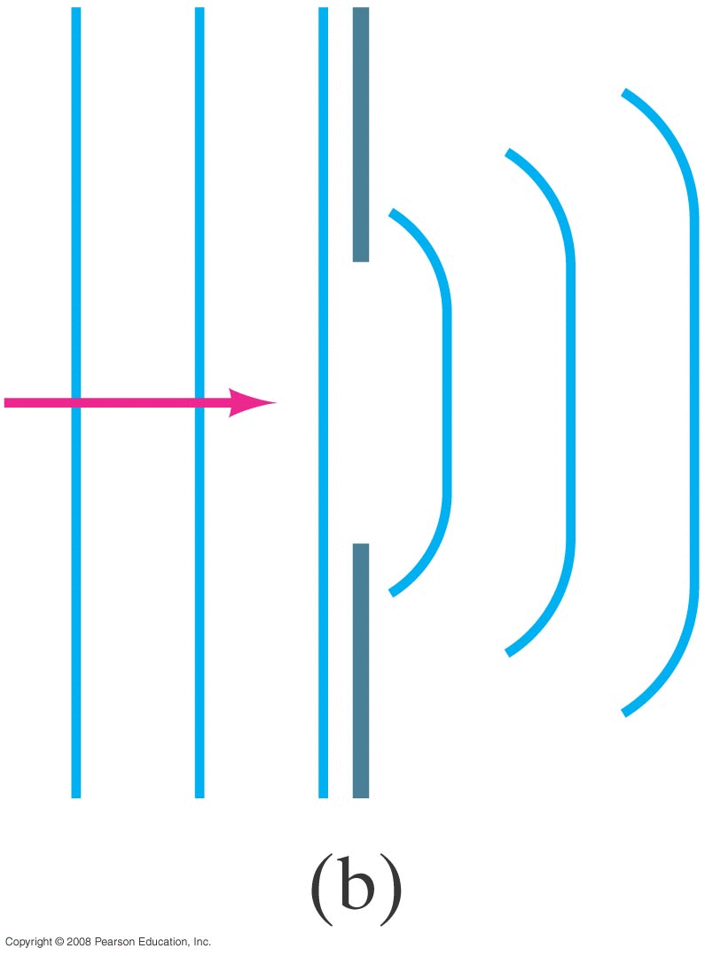
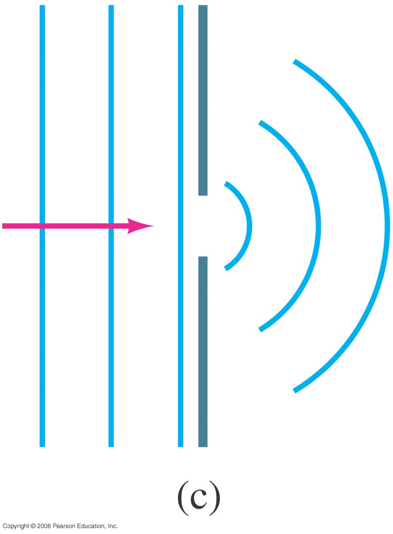
What happens when a wave (sound, light, water, ...) passes through an opening? • Ray Model: ray either goes through or not. • Wave Model (Huygen's principle) : every point on the wave front becomes another spherically expanding wave The wave diffracts around edges.
| |||
 |
 |
 |
 |
|
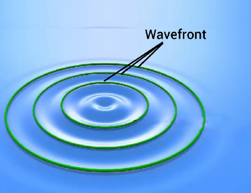
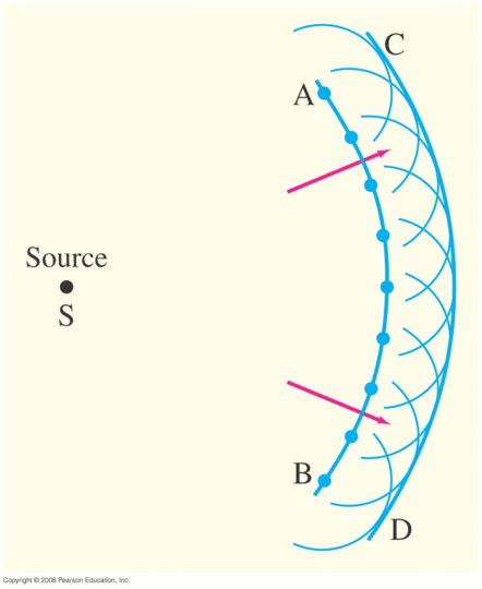
Snapshot of wave
|
Treat each point as a new 'point source'
|
||
|
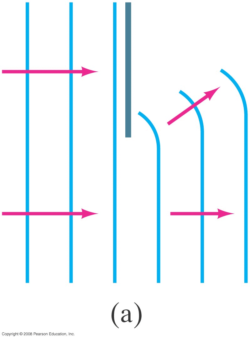
Wave passing through small hole
|
Wave passing through small hole
|
||
|
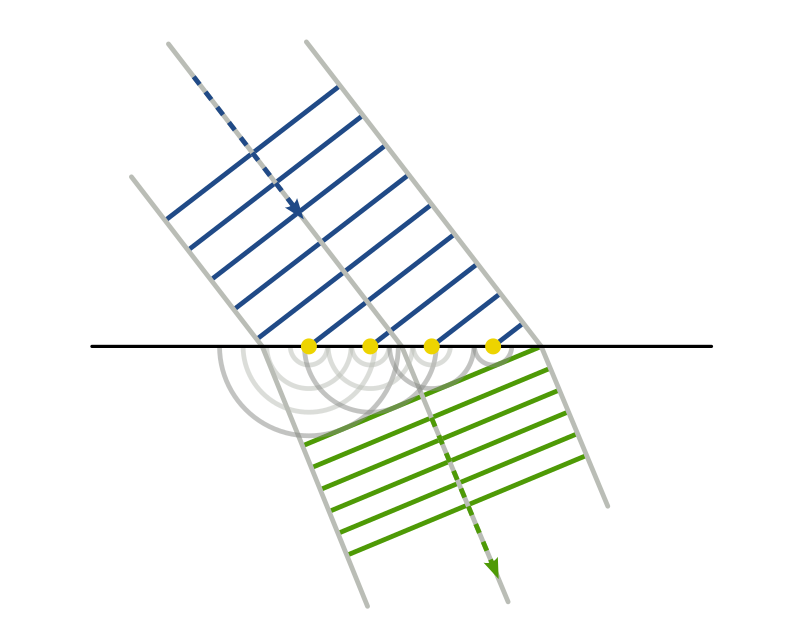
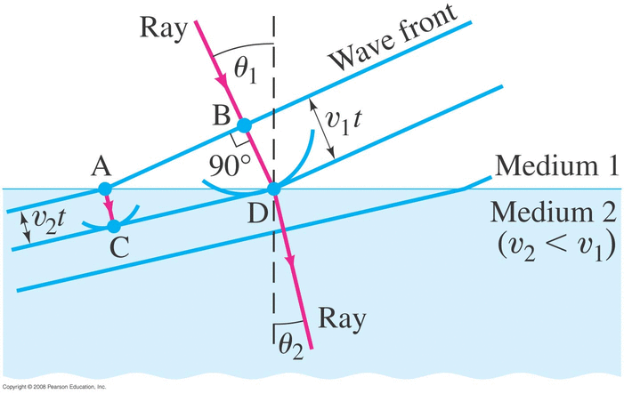
Snell's Law via Huygen
|
|||
|
What if 'v' isn't constant?
|
|
|
|
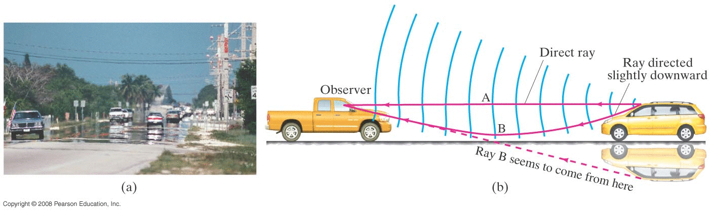
Mirage |
|
Hotter temperature near ground • lower air density • slightly lower index of refraction n • v=c/n so slightly higher speed of light near ground Apply Huygen's principle
|
Visible Light | ||||||||||||||||||||||||||||
|
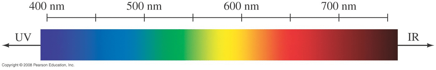
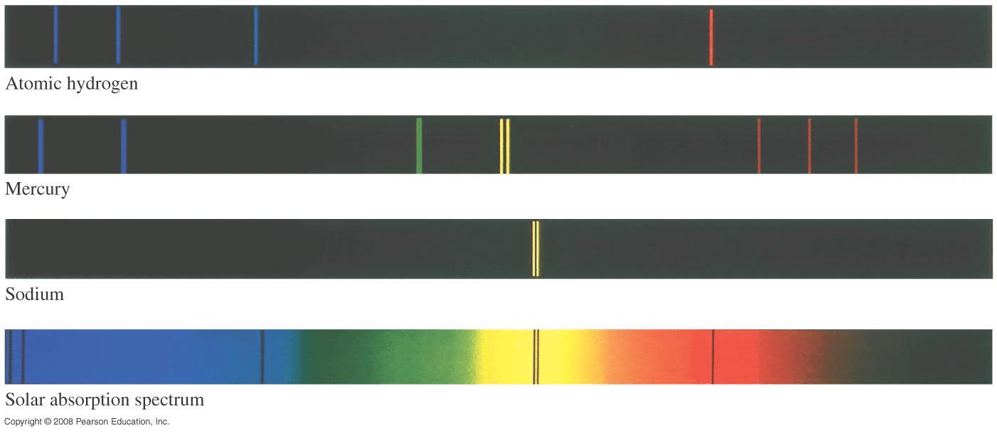
Visible Spectrum
v=λ/T=λf so f=c/λ Human range: λ = 380 nm = 380 X 10-9 m f=7.9 X 10¹⁴ Hz λ = 750 nm = 750 X 10-9 m f=4.0 X 10¹⁴ Hz |
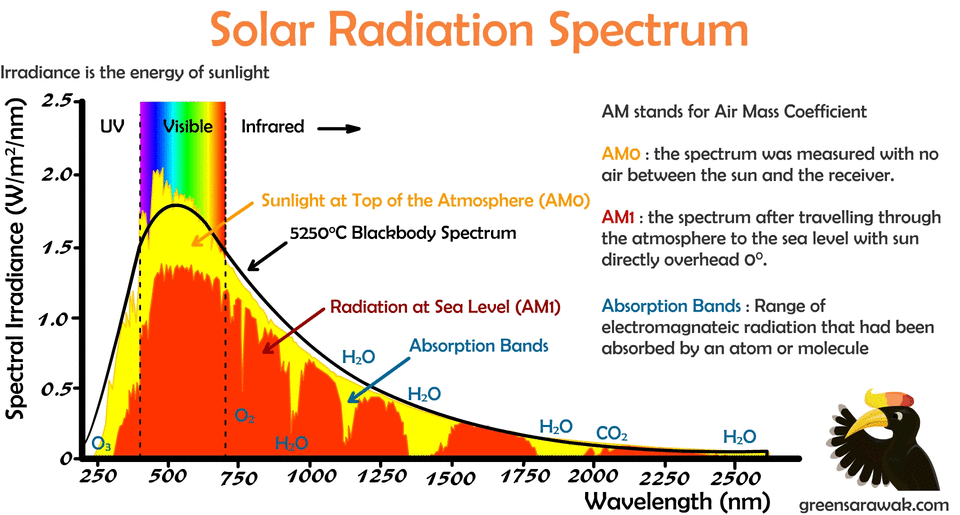
Spectrum of Sun
Another (formerly) common unit: Ångström 1 Å = 1X10⁻¹⁰ m = 0.1 nm 500 nm = 5000 Å
|
|||||||||||||||||||||||||||
Two-Source Interference (Review) | |
|
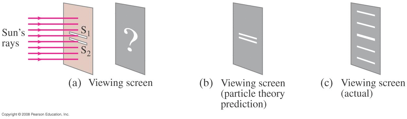
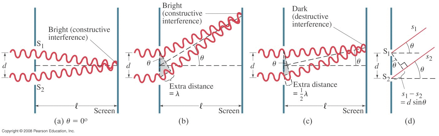
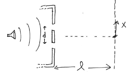
Single wavelength (frequency) of light (any wave really) coming in from the the left. Hits a barrier with two small openings. What should we 'see' (or 'hear' or 'measure') over on the right? (Ray vs Wave)
Wave model (interference)
Constructive Interference (strong signal, loud noise, bright light) occurs when: • path difference is an integer multiple of the wavelength involved: • (i.e. the two 'sine waves' arrive in phase) \[ | s_2 - s_1 | = m\lambda \] Destructive Interference (weak signal, quiet, dark...) occurs when: • path difference is an integer multiple plus 1/2 of the wavelength involved: • (i.e. the two 'sine waves' arrive exactly out of phase) \[ | s_2 - s_1 | = (m+\frac{1}{2})\lambda \] Far-field : if we're 'far away' from the two sources (i.e. l>>d then: \[ | s_2 - s_1 | = d\sin{\theta} \] (Realistically, it's "good enough" if the distance l is about 10 times the source separation d) |
Young's Double-Slit Experiment | |
|
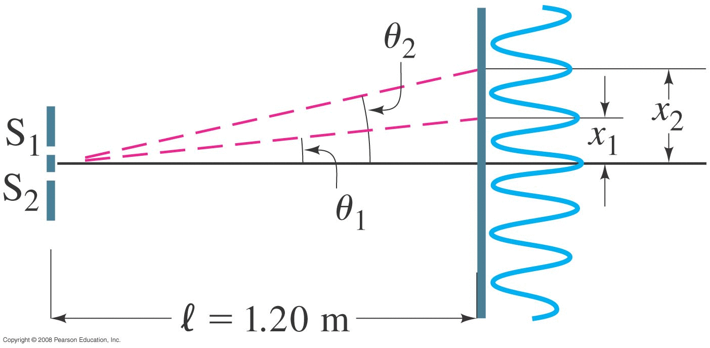
Source: light with λ=500 nm Two slits separated by d=0.1 mm Screen located l=1.2 m away.
Constructive (bright signal): \[ d\sin{\theta} = m \lambda \] \[ \sin{\theta} = m \frac{\lambda}{d} \] Physical locations of bright lines on screen: x = l * tan(θ) Note angles will be very small, so sin(θ)=tan(θ)=θ (in radians) x = l*θ = l*(mλ/d) = m ( λl/d ) Line spacing: Δx = λl/d
|
|
|
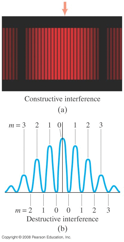
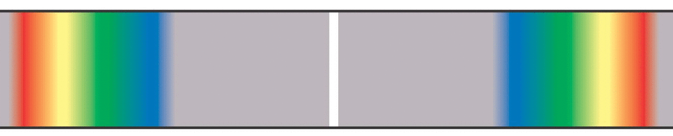
Note from above that x is directly and linearly proportional to λ. If we send in light with many wavelengths, we see the spectrum of that light:
|
|
|
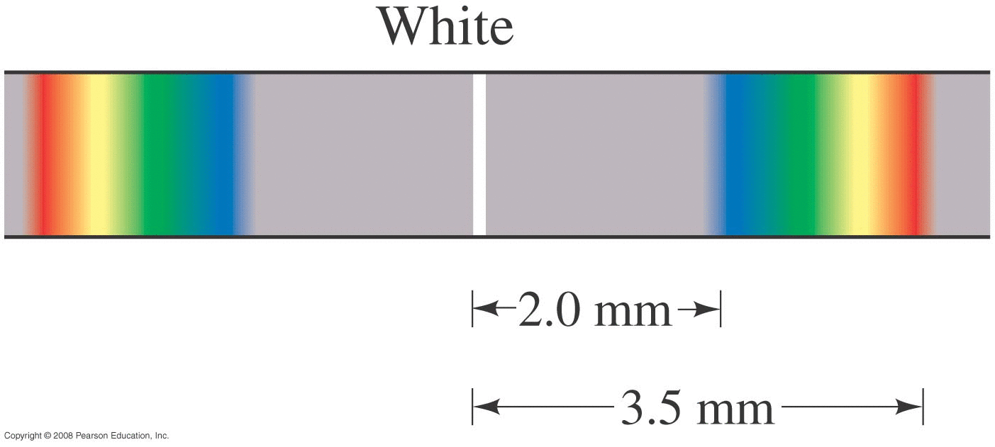
The problem of using this 2-slit geometry as an actual spectrometer is that each wavelength (color) doesn't appear at a specific location (angle), but gets spread out. • A specific 450 nm (blue) spectral line doesn't appear as a single bright (blue) line on the screen, but a spread-out blue blob • A specific 650 nm (red) spectral line becomes a spread-out red blob on the screen.
|
|
Single Speaker, Two Open Windows | |
|
Consider a 500 Hz tone coming from a speaker in a room with two (narrow) open windows separated by 1 m. What intensity (loudness) pattern will we have? Assume FAR FIELD but NOT small angle. (Why can't we use the `small angle' approximation here?) vsound=343 m/s so 500 Hz corresponds to λ=v/f=344/500=0.688 m. We need d>>λ to be able to use the "small angle" approximation but here d=1 m and λ=0.688 m so the d>>λ test fails.) |
|
Wireless Router | |
|
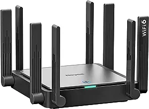
Consider a wireless router operating at 2.4 GHz. This particular router has two antennas separated by 6.25 cm. Where will the users see strong and weak signals?
Note: v=λ/T=λf so λ=v/f=c/f =12.5 cm Far field requires us to be at least 10 X farther away than the separation distance of the two sources. Small angle requires d>>λ |
|
Intensity I(θ) | |
|
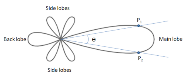
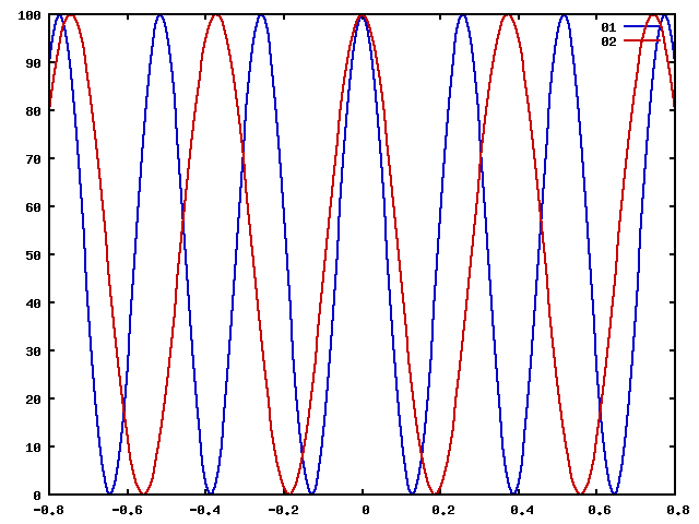
What we did above just tells us where complete constructive and destructive interference will occur. What about between those angles? How does the signal strength vary with angle?
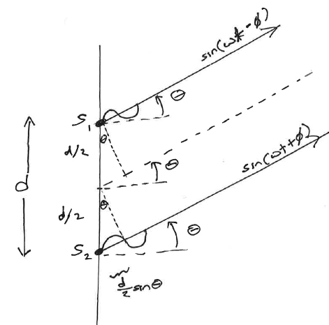
Using the dotted line as a reference: • signal 1 is shifted ahead by a physical distance of (d/2)sin(θ) • signal 2 is shifted behind by a physical distance of (d/2)sin(θ) Combined signal over to the right? E(t)=Eo [ sin(ωt+φ) + sin(ωt-φ) ] Trig identify to combine: E(t) = 2*sin( ωt )*cos(φ) Intensity proportional to amplitude squared We'll have (nominally) a double strength signal at the given frequency, with it's amplitude reduced by a factor: cos2(φ)
|
|
|
Relating path difference to phase shift φ: A physical shift of one wavelength represents a phase shift of 2π radians, so a physical shift of (d/2)sin(θ) represents a phase shift of:
\[ \phi = \frac{d}{2}\sin{\theta} \times \frac{2\pi}{\lambda} \] or: \[ \phi = \frac{\pi d}{\lambda} \sin{\theta} \]
Ultimately then: \[ I(\theta) = I_o \cos^2 \phi \hspace{2em} where \hspace{2em} \phi = \frac{\pi d}{\lambda} \sin{\theta} \] |
|
|
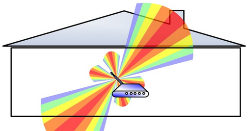
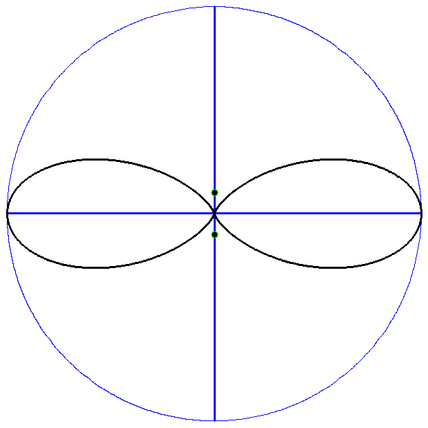
Our router operating at 2.4 GHz
|
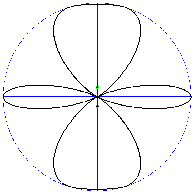
Same router operating at 5.0 GHz
|
|
What if we want better coverage? More antennas!
|
|